Creating a Program to Switch Data Types
The first step in creating a program to switch between two different data types is to create two case structures. Inside these structures there are sub diagrams. The purpose of the case structure is to determine which diagram will
execute when the program is ran. Then I added a switch to tell which program to execute. The two programs I added were to insert an image and to insert an excel file which gives me a graph. The displays for the VI’s need to be outside of the case structure. For my case it is the xy graph icon and the picture icon. It is also important to note that I want the structure to only run when the switch is in the true position. To accomplish this I can only create a VI when the case structure says true, and since I do not have a VI when the case structure says false I need to use the default if not wired between the display icon and the case structure. Also note these VI’s were built before this program was built. A picture of the program can be seen below.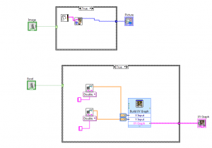
The top program is to insert an image on the front panel. On the left the switch can be seen. While the VI is inside of the case diagram. The bottom program is to insert an excel file and display a graph on the front panel.